The iPhone 4 Antenna
New types of antenna are being invented all the time. Existing types of antenna are constantly being adapted to new roles. But, in most cases these efforts aren’t successful, most new antennas are outperformed by existing designs. The existing well-known types of antenna have their own niches. When designers attempt to apply them outside their normal niches in other niches where other antenna types predominate this usually fails. Even if the antenna works in its new application its normally found that the type normally used in that niche can outperform it. These stories are the tails of the failure of many research programmes and start-up companies.
The new antenna in the iPhone 4 is surprising and impressive because it’s designers have overcome these barriers. Most new handsets use one of the common types of antennas, the monopole, the vertical helix (or stubby) antenna or the PIFA. The antenna design is almost always new for every new handset, but it’s based on an existing archetype. When a new type of antenna being developed it will normally be released first in an obscure low-volume product.
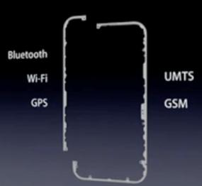
In the iPhone 4 Apple have imported a new type of antenna into the handset niche. They’ve done this on their headline product, not just some minor experimental product that could fail without financial consequences. Steve Jobs mentioned the antenna in his keynote speech, he said that the stainless steel rim around the edge of the phone forms the antenna. He put up a slide showing it:

This slide doesn’t make it clear what type of antenna we’re dealing with here because it doesn’t show the feeds or the ground-plane. I think I’ve figured it out though by looking through some of Apple’s patent submissions. Apple have patented a lot of antenna designs, but two patents in particular looks very like the antenna in the iPhone 4 slides and teardowns on the internet. The first is US patent application #20100123632 and the second a granted US patent #7551142 and these describe types of slot antenna.
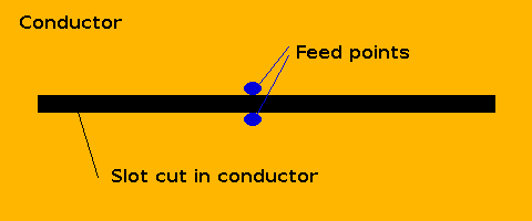
Like most patents it doesn’t describe the relevant ideas very clearly. So, I’ll explain it in my own way…. A normal slot antenna is a narrow rectangular hole cut in a large conductive surface.

The slot antenna is closely related to the dipole, it is the “complement” through the Babinet-Booker principle of the dipole. There’s an analysis of slot antennas from this perspective in Kraus & Marhefka. These simple slot antennas are used in antenna arrays for radars and various other types of electrically large antennas. But, they aren’t generally used for electrically small antennas. (Some folks may know of “slotted-PIFAs” these are PIFA antennas with slots in them but they aren’t slot antennas their design is very different). Slot antennas can be dielectrically loaded by filling the slot with a dielectric material such as plastic or ceramic.
The patent application suggests that Apple have designed a slot antenna that runs around the edge of the handset. The introduction says:
The antenna may be a slot antenna having a dielectric slot opening. The slot opening may have a shape such as a U shape or an L shape in which elongated regions of the slot run parallel to the edges of the portable electronic device. The portable electronic device may have a housing with conductive sidewalls. The conductive sidewalls may help define the shape of the slot. Antenna feed arrangements may be used to feed the slot antenna in a way that excites harmonic frequencies and that supports multiband operation while being shielded from proximity effects.
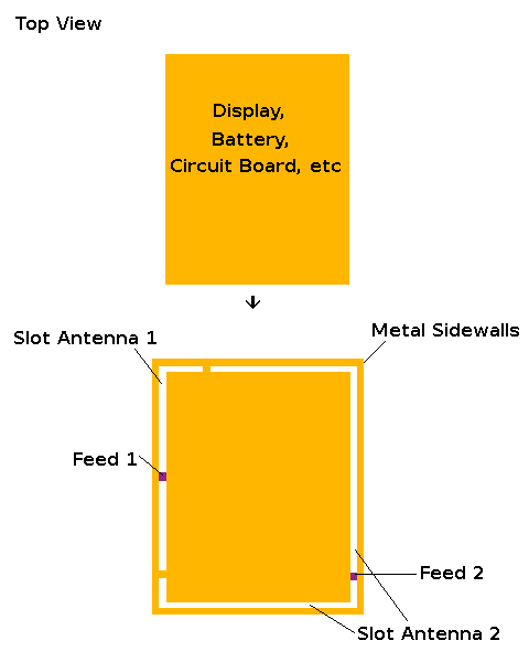
In the middle of phone there is a circuit board, battery, and display. All of these can be connected together, so that at RF frequencies they behave quite like a large block of conductive metal. This is common practice in handsets, as far as I can tell this is what’s being done in the iPhone 4. Around that there is a metal sidewall. The patent suggest that using a configuration like this slot antennas can formed from the gap between the metal sidewall and the internal conductive block.

The diagram above shows too slots both feed slightly off centre. One runs around the top and left side of the handset and the other around the rest. There are several ways of feeding such an antenna and the patent describes some of them. The simplest is a feed between the sidewall and main chassis driving a voltage between them. In the diagram above I’ve put on feeds and places where the slots end, these are just an illustration of the principle. I don’t know for sure if Apple have used this patent, if they have I don’t know where the feeds are. The patent explains that non-conducting front and back covers can be used to conceal and protect the antennas and internal electronics. Since these are covers of a dielectric material, that means there will be some dielectric load, and the antennas will be dielectrically loaded slots.
There’s lots more to talk about here. I haven’t covered much of the ideas in patent #7551142, I’ll do that in a future post. If I have time I’ll compare this to more conventional types of antennas like PIFAs. Also, I’ll comment on the problems recently uncovered with iPhone reception very soon.

