A General Equation for the Blocking Problem

With a problem like blocking the engineer has to come up with an equation to fit the details of the problem. A good approach is to start off with a general equation and work from there. We can work out what the equation should look like by considering the parameters we need.

To do this I’ll start at the radio being blocked, the victim, and work backwards. At some particular power the performance of the victim receiver will fall due to blocking. Let’s call that X.

X = Blocking power in dB at the victim receiver which will affect the system performance.

How much power gets to the victim receiver though? Going from the victim receiver there will be a cable or feeding network, then an antenna.

L1 = Loss of circuits and interconnects between victim receiver and the antenna it is connected to.

Instead of going into great detail about the antennas here I’ll just define an aggregate figure…

C = Coupling between the antenna of the victim receiver and the antenna of the blocking transmitter. This is a coupling between the two antenna ports.

Then we have a loss corresponding to L2 at the other side…

L2 = Loss of circuits and interconnects between blocking transmitter and the antenna it is connected to.

And finally…

P = Power output of the blocking transmitter.

These parameters lead directly to the equation we need:
P – L2 – C – L1 = Y

If Y > X then there will be system performance degradation due to blocking.

The mismatch loss associated with the transmitter and receiver can be put into L1 and L2. All of the parameters I mention vary across frequency, the frequencies that are relevant here are those that the blocking transmitter produces.

The Problem with LTE

In my opinion the architects of LTE have made some mistakes, this isn’t uncommon, many new protocols have had problems in their early days. The system they have created is susceptible to front-end blocking in particular bands.

Consider the band layout:
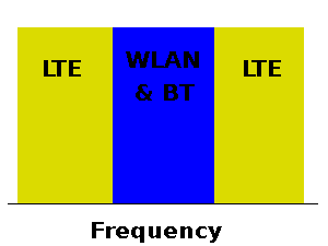
* LTE band 7 will operate from 2500 MHz to 2690MHz. This is split into an uplink band from 2500MHz to 2570 MHz and a downlink band from 2620 MHz to 2690 MHz.
* LTE band 40 will operate from 2300 MHz to 2400 MHz.

In between these bands is the 2.4GHz ISM band, which runs from ~2.4GHz to ~2.5GHz, the exact frequencies of edges of the band depend on the country. Many systems use this ISM band, WiFi and Bluetooth use it. More obscures systems such as video transmission systems and proprietary wireless keyboard and mice use it.

The diagram below shows the situation:

Yesterday I described the front-end blocking problem in general terms. You don’t have to be an RF genius to understand the problem the LTE architects have created here. The front-end receivers for LTE band 7, LTE band 40, WLAN, Bluetooth are fairly wideband, they will each respond to signals from all of the bands I’ve shown in the diagram.

GSM and WCDMA are “one band at a time” radios. When a GSM radio is using the 900MHz band it doesn’t use the 1800MHz band, or any other band, at the same time. The baseband controllers switches the radio between the various bands, sometimes it does this so fast that it can receive from the 1800MHz band while in call on a 900MHz band. This is achieved by time-division though, the radio never uses both bands at the same time. LTE radios are the same, that means that if a device is transmitting on LTE band 7 then it will not be receiving on LTE band 40. There is little chance of blocking problems within the LTE system.

However, the other radio systems involved, such as Bluetooth and WLAN, are controlled by completely separate baseband controllers. Let’s suppose there is a cellphone that has LTE band 7 and Bluetooth. When the Bluetooth module transmits then that signal will be transmitted from the Bluetooth antenna and received by the LTE antenna from there it will then enter the LTE receiver. Let’s suppose the base-station is transmitting to that same LTE receiver at the time too. As I described in my earlier post on blocking the front-end is unlikely to be able to cope with both of these signals. This will probably result in the LTE information being destroyed. The same applies in the opposite direction, the LTE transmissions can block nearby WLAN and Bluetooth receivers, especially if both are integrated into the same device.

In future posts I’ll discuss what can be done about this.

Antennas for Portable Handsets

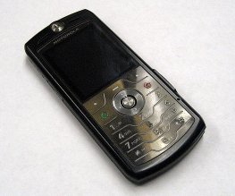
.Cellphone Image

My first job in Antenna design was designing internal antennas for cellphones. The cellphone market is enormous and every handset needs at least one antenna, and often two. It’s important for many of the people involved to understand the problems, so this is a very basic overview.

Due to the differences between handsets nearly every new model requires a new bespoke antenna design. The volume allotted for the antenna is different in each new handset, and it’s a different shape. The circuit board and the metal parts of the handset provide a groundplane for the antenna. This groundplane generally changes in size and shape with every new model. The groundplane characteristics affect the antenna significantly. An antenna built for a particular groundplane will not work well on a groundplane with a different size and shape. The plastics surrounding the antenna, and other nearby components also affect the antenna’s parameters.

Because of these issues it is virtually impossible to reuse designs directly. It can sometimes be done with external antennas such as whip antennas and stubby antennas, but not with the internal antennas commonly used today. It can sometimes be done with Bluetooth and Wi-Fi antennas, but not often with the main antenna for the cellular service.

So, Antenna Designers use a different sort of reuse. They gather knowledge about certain types of antennas, such as PIFAs and sub-types of them, they then learn how those sub-types behave and what factors affect their performance. An Antenna Designer learns how to “tune up” a few types of antenna. This allows him or her to quickly respond when given a particular product to work on.

To make this process as efficient as possible the major antenna companies have invested in rapid prototyping equipment, rapid antenna measurement equipment and other infrastructure.