How to Avoid Hand Effect and Head Effect Problems in Handsets
The iPhone 4 has shown that hand effect problems can be very serious. This is generally true of antenna problems, I know of several handsets that were developed at huge cost and never shipped because satisfactory antenna performance couldn’t be achieved.
There are five directions this problem can be approached from:
- The Industrial Design direction. Some IDs are easier for antenna designers to work with than others.
- The Antenna Type – an antenna type can be picked that is more resistant to problems.
- Antenna placement – where in the handset the antenna is.
- Details of Antenna Design – just as some antenna types are better some features within antennas can be better or worse.
- Radio influences such as the radio and the band support can help.
Industrial Design
If the industrial designers and the antenna designers are prepared to be cooperative then that can help a lot. The industrial designers should to be flexible about the type and layout of the antenna. The antenna designers for their part should not try to build the easiest type of antenna possible, they should aide the industrial designers in achieving a good design. Generally the more cubic centimeters of space that are apportioned to the antenna the better the performance that the antenna designers can achieve on every spec. But, there are often more elegant ways to solve the problems than throwing CCs of space at them.
In some situations the industrial designer can design a case that encourages the user to hold the handset in a particular way. The case can encourage the user not to hold the antenna. For example, if there’s a bump around the rear-facing camera then the user is less likely to wrap their hand around it and the area above it.
Antenna Type.
The main types of antenna used in handsets are shown below:
- External
- Stubby or Helical
- Whip or Retractable
- Internal
- Antennas with a groundplane below them – PIFAs
- Antennas without groundplanes below them – Monopoles & Inverted-F antennas
Externals are rarely an issue these days, but they teach important lessons for internal antenna design. A retractable whip antenna is an external monopole that is parallel to groundplane and above it. The other main type of external is the stubby, these are a small round cylinder of plastic containing a type of shortened monopole antenna. Often stubby antennas are called “helicals” in books because it’s assumed that the antenna inside is a normal mode helix. Often though designers used other shapes, such as meanders. Anyway, both meanders and normal mode helicals are shortened monopole antennas. So, the two main types of external antenna, the retractable and the stubby are respectively a monopole and a shortened monopole. Investigations into these antennas years ago showed that the stubby antenna suffers more from the effects of the nearby head than the retractable. The reason for this is quite clear if you imagine a person holding a phone with both types of antenna. Part of the retractable antenna is close to the head, but all of the stubby antenna is close to the head. By compressing the antenna into a small space the stubby antenna creates a small space where the nearby dielectric materials have a large effect. So, stubbys suffer seriously from detuning problems, this problem carries over into internal antennas.
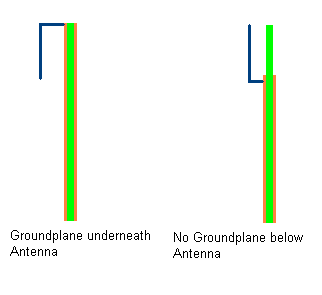
Internal antennas are often all called “PIFAs”, but the word is used for types of antenna that are really quite different to each other. Since PIFA means “planar inverted-F antenna” some people use it to refer to any antenna that has a feed and short pin that is made out of flat conductors. There are really at least two types though, firstly there are the sort built on top of a groundplane, those are somewhat like size-reduced patch antennas. Then there are the sort where the groundplane is parallel to the antenna but not underneath it, those are more like size-reduced monopole antennas. The diagram below is a side view of the internals of two handsets. The PCB material is in green and the groundplane is in orange.

The type with the groundplane underneath is what’s normally called a PIFA. The type with no groundplane underneath is closer to a monopole, even if it has a ground pin that only really affects the matching. Some types of normal mode helix have ground pins too. These two types of antenna have their advantages and disadvantages, it’s worth mentioning them all not only those connected with the hand & head effect problems.
- PIFAs with groundplanes underneath
- Pros
- Components can be put in the side of the opposite side of the groundplane to the antenna, and sometimes on the antenna side too.
- With many types of design radiation is directed away from the head especially in the high frequency bands. It’s not that difficult to meet SAR specifications.
- Dielectric objects, such as the head, don’t detune the antenna much if they’re behind the groundplane. Since that side of the groundplane doesn’t transmit much radiation blocking it with an absorbing object doesn’t cause that much signal to be wasted.
- Cons
- Generally require a lot of volume.
- The distance from the antenna to the groundplane is critical. That gap must be large for a multi-band antenna. But, the size of that gap directly affects the thickness of the handset.
- Difficult to design.
- Monopole-like antennas without groundplanes underneath
- Pros
- Generally require less volume than with-groundplane antennas.
- A bit easier to design.
- A multi-bands antenna doesn’t require a thick handset.
- Cons
- The PCB area around the antenna can’t be used. Other types of metal components often can’t be placed nearby because they cause detuning.
- The antenna detunes when a dielectric object is placed nearby at any side. The head causes more detuning compared to an antenna with a groundplane, and the hand generally does too.
- If the antenna is close to the head in the normal call position then the handset will probably fail the SAR tests.
The main lesson here is if you want the antenna to perform well in the presence of the head and hand then use an antenna with a groundplane.
Antenna Placement.
The conventional type of handset antennas I’ve discussed here only work well if they’re at the top of the handset or the bottom. They don’t work well in the centre of the PCB. So, the choice is between the top and bottom.
Generally users hold their phones by the bottom part, so hand detuning is worse if the antenna is at a the bottom. Sometimes the ID designers can help here by creating a case that encourages the user to grip the phone in a different way, but that’s difficult. Similarly, head detuning is generally worse if the antenna is at the top of the handset.
PIFAs with groundplanes below can be put at the top or bottom of a handset. If they’re put at the bottom then the user is likely to cover the antenna with their hand and cause serious attenuation and detuning. If the antenna is put at the top then the head is on the groundplane side not the antenna side, so it causes less detuning. So, this type of antenna should be put at the top.
The situation is different for antennas with no groundplane below them. These will generally fail the SAR test if they’re put at the top, so they have to be put at the bottom for that reason. This means that these type of antennas have a two-fold problem. They are sensitive to detuning by dielectric objects and since they generally have to be put at the bottom of the handset they are more likely to be close to the hand or even covered by it.
The main lesson here is to use a PIFA with a groundplane and put it at the top if you can. The situation for slide handsets and clamshell handsets is quite complicated, I might discuss that in the future in another post.
Details of the Antenna Design.
The closer the antenna is to the outside of the case the more it will be affected by proximity detuning. But, if the designer leaves a gap between the case and the antenna then that’s forsaking space and it will probably decrease the antenna’s performance in empty space. This trade-off has to be made on a handset-by-handset basis. It’s difficult and can require a lot of prototyping and simulation.
Another problem is areas of high E-field. Generally the sensitive parts of an antenna follow the E-field. If the E-field is high in a particular region then a dielectric object close to that place will cause a large frequency shift. It’s best to avoid creating such regions as much as possible, that can be done by widening out conductors on the antenna close to the high E-field region. Another possibility is to move the region further inside the handset.
There have generally been two theories about the iPhone 4’s problem. Firstly, lots of people online have said that dampness on the users fingers causes a conductive bridge over the gap in the case. As I said in previous posts I don’t think that’s very likely. Secondly, when the user touchs the gap that causes detuning. I think the detuning explanation is more likely, but the conduction explanation could be right, or it could be a bit of both. In either case this demonstrates a problem with putting the antenna on the outside of the case.
If GPS, Bluetooth or WLAN antenna is needed then it’s best to use a separate antenna for those bands. That helps the detuning problem because it makes the main antenna design easier.
Other Influences such as the Radio.
The output amplifiers in the transmitter part of the radio suffer from the problem of “load-pull”. The amplifier is built to work when applied to a particular output impedance which is generally 50 ohms. If the antenna’s input impedance is different than 50 ohms then there is mismatch loss. But, there’s also an additional loss caused because the amplifier’s performance degrades, this is load-pull.
Suppose due to detuning the VSWR on a particular channel gets worse, it goes from 3:1 to 2:1. The amplifer may not be able to supply full power when mismatched 2:1, so it’s power output may drop by a dBm or two. That would cause a big drop in performance. So, an amplifier with better load pull characteristics gives better performance when there’s detuning. This was a great problem in the early days of digital cellular in the 90s and early 00s, amplifiers then had much worse load-pull characteristics than those we have today. But, the problem has never completely gone away. (Exactly why it’s never gone away is a story for another time).
I’ve seen a few folks try to redesign the matching circuit to cope with detuning better. I’ve never seen this enterprise succeed though. I don’t think there’s much that matching circuits can do to overcome this problem.
ESD protection circuits are important if metal parts of the antenna are exposed to the user. The radio must be protected from static shocks that can occur if the user accumulates a charge by walking across a carpet for example.
Cellphones today cover many bands. A cheap European handset will cover the European GSM/EDGE bands at 900MHz and 1800MHz, the US PCS band at 1900MHz and the European WCDMA/UMTS band at 2100MHz. A cheap US handset will cover the US 800MHz and 1900MHz bands, GPS at 1575MHz and often the European 1800MHz band too. But, these handsets don’t compare to high-end Smartphones, those often support all of the bands I’ve mentioned above, that’s six bands. Such phones are called “world phones” because they support so many bands that they can be used almost anywhere there is a cellular network. Supporting all those bands requires a large antenna especially if a PIFA with a groundplane below it is used. This often results in detuning taking a back-seat in antenna design because band support becomes the big issue.
This problem can be solved by regional variants. The makers of cheaper handsets tend to make a US version and a European version. Most countries use the US or European band layout, so doing that provides a large market. These phones will still work if taken abroad because there is provision for that. For example, a typical European handset will work on the 1900MHz PCS band in the US, assuming the carriers involved have agreements. If Smartphone designers were to take this approach then they would have to build more handset variants, but it would make the antenna less difficult. It would make with-groundplane PIFAs more practical and they were used that would help prevent detuning.
A Concluding Thought…
If handset designers paid a little bit more attention to the issues above then the user experience would be better. From the user’s point of view “network coverage” would magically increase. But, users mostly blame networks for poor coverage rather than handsets. That means the handset companies often have little incentive to improve. But, after the well-publicised iPhone 4 problems users may be more critical of handsets in the future.


